A Deep Dive into 14 Essential Electrical Components
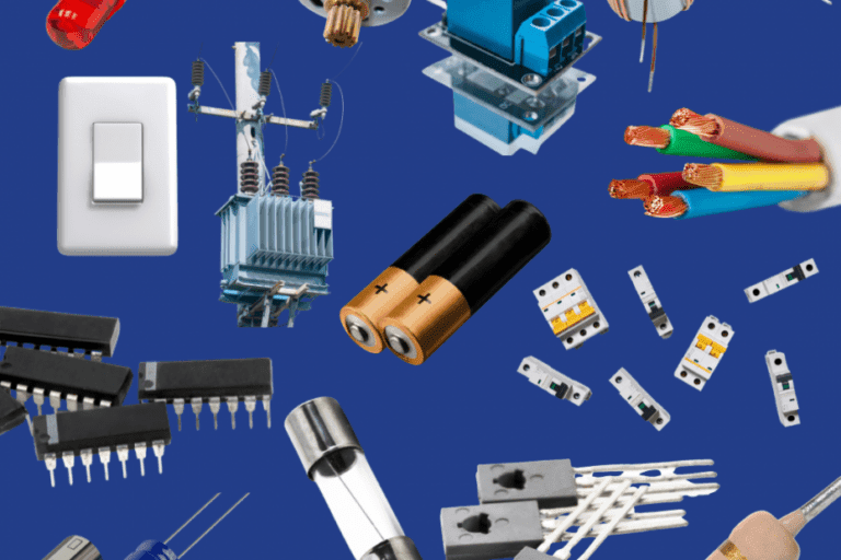
Electronics and electrical engineering are the driving forces behind many technological innovations shaping our modern world. Understanding the fundamentals of these fields requires a solid grasp of the essential electrical components and their functions. These electrical elements play a critical role in designing, building, and troubleshooting electronic circuits, from resistors and capacitors to transistors and diodes. We will take a deep dive into the 14 essential electrical elements and their functions, providing you with the knowledge and tools to become an expert in electronics. Whether youā€™re a beginner looking to build a strong foundation or an experienced engineer seeking to expand your knowledge, this guide has something for everyone.

1. Resistor

Electrical element: Resistors

AĀ resistorĀ is an electrical component that opposes the current flow in an electronic circuit. It is made up of a material with a specific resistance value, which determines the amount of current that can flow through it. Resistors are used to control the current flowing through a circuit, reduce voltage levels, and provide a load for transistors and other components.

Browse Resistors

Resistors come in various types, including a carbon film, metal film, wirewound, and surface mount. Depending on the application, they are also available in different resistance values and power ratings.

Calculating Total Resistance for Series-Connected Resistors

When resistors are connected in series, calculating the total resistance is straightforward. Simply, you add up the individual resistances of each resistor in the series.

Here’s a quick breakdown:

  1. Identify Each Resistor’s Value: Check the resistance values of each resistor you’re working with. These are often labeled as ( R_1 ), ( R_2 ), ( R_3 ), and so on.
  2. Summing the Resistances: Total resistance, denoted as ( R_{total} ) or ( R_t ), is the sum of all individual resistances in the series. Mathematically, it looks like this:

[ R_t = R_1 + R_2 + R_3 + \ldots + R_n ]

  1. Example Calculation: If you have two resistors in series, one with ( 10 , \Omega ) and another with ( 15 , \Omega ), the total resistance would be:

[ R_t = 10 , \Omega + 15 , \Omega = 25 , \Omega ]

Key Points to Remember:

  • Series Connection: Resistors are in series if they are connected end-to-end, providing a single path for current flow.
  • Cumulative Effect: Adding more resistors in series increases the total resistance.
  • Ohmā€™s Law Compatibility: The total voltage across the resistors is the sum of the voltages across each resistor.

By following these steps, you can effortlessly determine the total resistance for any number of resistors connected in series.

Calculating Total Resistance for Resistors in Parallel:

When resistors are connected in parallel, calculating the total resistance involves combining them in a particular way. Instead of adding their resistances, you use their reciprocal values.

  1. Identify Individual Resistances:Ā Start by knowing the resistance of each resistor in ohms (Ī©). Let’s call them ( R_1 ) and ( R_2 ).
  2. Use the Parallel Resistance Formula:

The formula to find the total resistance ( R_{\text{total}} ) in a parallel circuit is:

[ \frac{1}{R_{\text{total}}} = \frac{1}{R_1} + \frac{1}{R_2} ]

  1. Calculate Reciprocals:Ā Calculate the reciprocal (1 divided by the resistance value) for each resistor.
  2. Sum the Reciprocals:Ā Add these reciprocal values together.
  3. Find the Reciprocal of the Sum:Ā The total resistance is the reciprocal of this summed value.

This method ensures that the total resistance is always less than the smallest individual resistor. For circuits with more than two resistors connected in parallel, extend the formula by adding more reciprocal terms corresponding to each additional resistor. This approach is crucial for designing efficient electrical systems, ensuring they operate safely and perform as expected.

2. Capacitor

electrical element: Capacitor

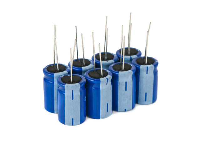
A fundamental piece of electronic equipment, aĀ capacitor, is an energy storage unit that utilizes an electric field. It comprises two metallic plates divided by a dielectric material, such as ceramic, polyester, or electrolytic. Energy is stored when voltage is applied to the capacitor. Its applications are diverse, such as reducing noise and ripple in power supplies, timing circuits, and circuits that need to be tuned.

The variety of capacitors available is extensive, including ceramic, electrolytic, tantalum, and film capacitors that suit different capacitance values and voltage ratings depending on the intended applicationā€™s requirements.

Browse Capacitors

Understanding Charge, Voltage and Capacitance

The relationship between charge, voltage and capacitance in capacitors allows capacitors to store electrical energy effectively. Hereā€™s how charge, voltage, and capacitance interrelate:

  • Charge (Q): This is the amount of electric charge stored on each plate of the capacitor. One plate holds a positive charge (+Q), while the opposite plate holds a negative charge (-Q).
  • Voltage (V): Voltage refers to the electric potential difference between the two plates of the capacitor. The greater the charge difference, the higher the voltage.
  • Capacitance (C): Capacitance is a measure of a capacitor’s ability to store charge per unit voltage.

It’s defined by the equation:

[ C = \frac{Q}{V} ]

where ( C ) is capacitance in farads (F), ( Q ) is the charge in coulombs (C), and ( V ) is the voltage in volts (V).

Key Takeaways:

  • Direct Proportionality: The voltage across the capacitor plates is directly proportional to the amount of charge stored. In other words, as the charge ( Q ) increases, the voltage ( V ) also increases.
  • Capacitance Value: The capacitance value (C) remains constant for a given capacitor. It depends on factors like the surface area of the conductive plates and the distance between them, as well as the properties of the insulating material.

3. Inductor

Electrical element: inductor

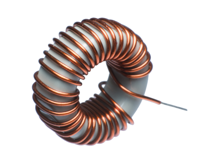
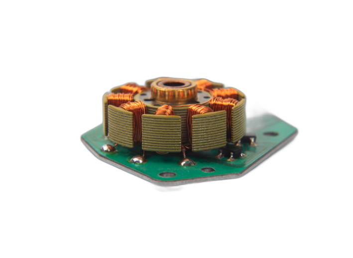
InductorsĀ are like tiny electrical storage units capable of holding energy in a magnetic field. They consist of a coil of wire that creates a magnetic field when electricity passes through it. These beneficial components have many applications, from filtering out unwanted noise from power supplies to control motors.

Browse Inductors

Voltage-Current Relationship in Inductors

The voltage-current relationship in inductors can be understood by analyzing the magnetic field.

Key Points:

  • Magnetic Field Dynamics:Ā As the current varies, so does the magnetic field within the inductor.
  • Magnetic Flux:Ā The changing magnetic field alters the magnetic flux that links with the coil’s loops.

This change in magnetic flux induces a voltage across the inductor, a phenomenon explained by Faraday’s Law. Additionally, Lenz’s Law specifies that the induced voltage will act to oppose the change in current. The relationship is mathematically expressed as:

[ V = L \frac{dI}{dt} ]

Here:

  • (V)Ā denotes the voltage across the inductor.
  • ( L )Ā stands for the inductance, measured in henries (symbol: H).
  • ( \frac{dI}{dt} )Ā represents the rate of change of current through the inductor.

Practical Implications

  • Circuit Behavior:Ā In practical terms, if the current through an inductor changes rapidly, a higher voltage will be induced. Conversely, a slow change in current results in a smaller induced voltage.
  • Component Selection:Ā Understanding this relationship helps in selecting appropriate inductors for different applications, ensuring that circuits function efficiently and safely.

By analyzing the voltage and current relationship in an inductor, you can better design and troubleshoot electronic circuits, ensuring optimal performance and longevity.

Although they all serve the same primary function, inductors come in various sizes and types, including air-core, iron-core, and toroidal inductors. And not all inductors are created equal ā€“ certain types can handle higher currents than others, and some are better suited for specific applications.

4. Diode

Electrical element: Diodes

Diodes are electrical conductors that only allow current to flow in one direction. These small components comprise a special combination of semiconductor materials that provide practical applications in electrical engineering. With the ability to rectify AC signals into DC, protect circuits from reverse voltage, and regulate voltage, diodes are an integral component in many circuits. Choose from various types, from silicon to germanium to Schottky diodes, and match the voltage and current rating to your specific application. Embrace the power of diodes and discover their many uses in your projects.

Vf and Vb

When discussing diodes, forward conduction voltage (Vf) and breakdown voltage (Vb) are crucial parameters that define their operational behavior.

Forward Conduction Voltage (Vf)

The forward conduction voltage is the minimum voltage that must be applied to the diode in the forward direction to make it conduct electricity efficiently. This voltage threshold ensures that the diode allows current to pass through with minimal resistance. For instance, a red LED might need a minimum of approximately 1.8V to light up effectively. Below this voltage, the diode wonā€™t conduct well, and in practical scenarios, may not function as intended.

Breakdown Voltage (Vb)

On the flip side, the breakdown voltage is essential for understanding the diode’s limits in the reverse-bias condition. When a reverse voltage is applied, the diode ideally blocks current up to a certain point. The breakdown voltage is this crucial threshold beyond which the diode will start to conduct in reverse, often resulting in a sharp, destructive current surge. For example, if the reverse voltage applied to a diode exceeds its breakdown voltage, it could lead to permanent damage due to overheating or electrical breakdown.

Practical Implications

  • Forward Direction: In applications like LED lighting or rectifiers, ensuring the voltage applied is above the forward conduction voltage is key to proper operation. Under normal conditions, this ensures efficient current flow with minimal resistance.
  • Reverse Direction: Understanding the breakdown voltage is vital for protecting circuits. Diodes can be intentionally operated just below their breakdown voltage to prevent damage in sensitive electronic components.

5. Transistor

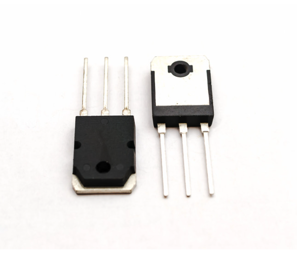
A transistor is a complex component amplifies and switches electronic signals with precision and speed. The secret to its success lies in its intricate design, which involves doping semiconductor materials like silicon or germanium to create p-type and n-type regions. Transistors find usage in various applications, ranging from amplifiers and oscillators to digital circuits. Understanding the different types of transistors, such as bipolar junction transistors, field-effect transistors, and insulated-gate bipolar transistors, is crucial to select the correct voltage and current ratings for the job.

Transistor Pins and Their Functions

To grasp how transistors work, itā€™s essential to understand the function of their three pins: the Collector (C), Base (B), and Emitter (E).

Collector (C)

The Collector pin is where the main current enters the transistor. This pin is primarily responsible for collecting electrons or holes, depending on the type of transistor. Itā€™s one of the two paths through which the electrical current flows when the transistor is in its “on” state.

Base (B)

The Base pin controls the transistor’s operation. Think of it as the gatekeeper. By applying a small voltage to the Base, you can regulate the current flowing between the Collector and the Emitter. This makes the transistor act like a switch or an amplifier, depending on the application.

Emitter (E)

The Emitter pin is the exit point for the current. Itā€™s connected to the circuit ground or the lower potential side, completing the path for the electrical current flowing from the Collector. When a sufficient voltage is applied to the Base, the Emitter allows the current to flow through the transistor.

How It Works

  • Zero Voltage:When there is no voltage applied between the Base and ground, the transistor remains off, meaning no current flows between the Collector and the Emitter.
  • Small Voltage:When a small voltage (typically around 0.6V for some transistors) is applied between the Base and the Emitter, the transistor switches on and permits current to flow from the Collector to the Emitter.

These functionalities make transistors indispensable in a wide array of electronic applications, from simple switches to complex amplifying circuits.

6. Integrated Circuit (IC)

electrical element: integrated circuit

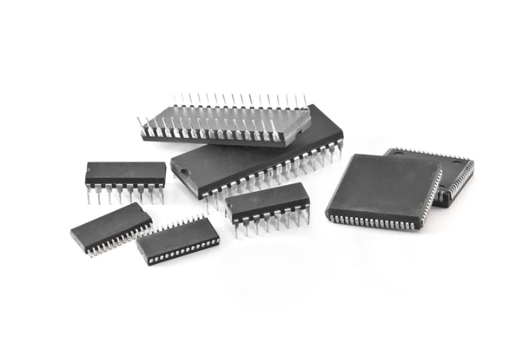
Integrated circuitsĀ (ICs) Ā are the powerhouse of hundreds of electronic devices we use daily. Imagine an entire electronic circuit in a tiny piece of semiconductor material, typically silicon. These micro wonders harness the power of interconnected diodes, resistors, transistors, and capacitors, all etched onto a single chip. This miniaturization allows for the creation of complex circuits that can perform a wide range of functions, from simple amplification to complex data processing.

Browse Integrated Circuits

Thanks to their versatility, ICs are used in everything from microprocessors, which serve as the brains of computers and smartphones, to memory chips that store data, and analog circuits that handle real-world signals like sound and radio waves. There are various types of ICs, including digital ICs, which process binary data, and analog ICs, which handle continuous signals. Some ICs, known as mixed-signal ICs, combine both digital and analog functions on a single chip.

The packaging of ICs is also diverse, with options including through-hole and surface mount types, each suited to different manufacturing processes and applications. Through-hole packages are typically used in applications where mechanical strength is important, while surface mount packages are favored for their compact size and ease of automated assembly. The number of pins on an IC package can vary widely, from just a few to several hundred, depending on the complexity of the circuit and the number of connections required.

ICs have revolutionized the electronics industry by enabling the mass production of reliable, high-performance electronic devices at a low cost. This has led to the proliferation of electronic gadgets and systems that are integral to modern life, from household appliances and medical devices to industrial machinery and telecommunications infrastructure.Ā The continuous advancement in IC technology, driven by Mooreā€™s Law, has resulted in ever-smaller, faster, and more efficient chips, fueling innovation across all sectors of the economy.

Common Types of Integrated Circuits

Integrated circuits (ICs) come in various types, each serving specific functions in electronic devices. The most common types includeĀ digital ICs,Ā analog ICs, andĀ mixed-signal ICs. Digital ICs, such as microprocessors and memory chips, process binary data and are fundamental to computers, smartphones, and other digital devices. Analog ICs, like operational amplifiers and voltage regulators, handle continuous signals and are used in applications such as audio processing and power management. Mixed-signal ICs combine both digital and analog functions, making them ideal for complex tasks like signal conversion in communication systems.Ā Additionally, ICs are classified based on their integration scale:Ā SSI (Small Scale Integration),Ā MSI (Medium Scale Integration),Ā LSI (Large Scale Integration), andĀ VLSI (Very Large Scale Integration), which indicate the number of gates or transistors on a chip. This diversity in types and scales allows ICs to be tailored for a wide range of applications, driving innovation across various industries.

7. Transformer

A transformer is a versatile and essential electrical component at the heart of the electrification world. It has two coils of wire encircling a magnetic core, and when the voltage changes in one coil, it induces a different voltage in the other coil. This fundamental principle enables transformers to regulate voltage, match impedance, and isolate circuits for various applications. From step-up to step-down and isolation to autotransformers, transformers come in multiple types to fulfill specialized needs. Additionally, they come in a range of power ratings to cater to specific application requirements.

Browse Transformers

Ideal vs Real Transformers

Transformers play a crucial role in electrical systems by stepping up or stepping down alternating voltages through electromagnetic induction. However, there are key differences between ideal and real transformers that affect their efficiency and performance.

Ideal Transformers

  • Perfect Energy Transfer: In an ideal transformer, 100% of the electrical power input to the primary coil is transferred to the secondary coil. No energy is lost as heat or other forms of dissipation.
  • No Power Losses: Ideal transformers assume no losses, meaning there are no resistive, hysteresis, or eddy current losses in the core or windings.
  • Simple Equations: The relationship between the primary and secondary voltages is directly proportional to the ratio of the number of turns in the primary coil to the number of turns in the secondary coil:

[ \frac{V_s}{V_p} = \frac{N_s}{N_p} ]

Where ( V_s ) and ( V_p ) are the secondary and primary voltages, respectively, and ( N_s ) and ( N_p ) are the number of turns on the secondary and primary coils.

Real Transformers

  • Energy Loss: In real transformers, there are various types of energy losses. Heat is generated due to the resistance of the wire (copper losses), and additional losses occur due to magnetic hysteresis and eddy currents within the core.
  • Efficiency: Real transformers do not achieve 100% efficiency. Typically, they operate at around 95-99% efficiency, depending on the quality and design.
  • Complex Calculations: To account for losses, real transformers require more complex equations and considerations, such as including core losses and winding resistance in their efficiency calculations.
  • Material Impacts: The efficiency and effectiveness of real transformers are also influenced by the materials used for the core and the wire. High-quality materials can reduce losses but usually at a higher cost.

Key Takeaways

  • Ideal transformers are theoretical modelsĀ that assume perfect energy transfer without any losses.
  • Real transformers experience inevitable losses, resulting in less than 100% efficiency.
  • Understanding these differences is crucial for designing efficient electrical systems and choosing the right transformer for your needs.

By comprehending both ideal and real transformer principles, engineers and technicians can better predict performance and improve the design of electrical systems for various applications.

8. Relay

electrical elements: relay

A relay is an electrical component that switches high currents or voltages using a low-current control signal. It is made up of a coil of wire that generates a magnetic field when a current flows through it. This magnetic field activates a set of contacts, which can open or close a circuit. Relays are used in various applications, such as motor control, power switching, and automotive systems. They are essential in situations where it is necessary to control a high-power circuit with a low-power signal, providing isolation and protection for sensitive control circuits.

Browse Relays

Relays come in various types, including electromechanical, solid-state, and reed relays.Ā Electromechanical relaysĀ use a physical moving armature to open or close contacts, making them suitable for a wide range of applications due to their robustness and reliability.Ā Solid-state relaysĀ (SSRs) use semiconductor components to perform switching without moving parts, offering faster switching times and longer operational life, ideal for high-speed and high-frequency applications.Ā Reed relaysĀ consist of reed switches enclosed in a glass tube and activated by an electromagnetic coil, known for their fast response time and suitability for low-current applications.

Depending on the application, relays are available in different contact and voltage ratings. For instance,Ā contact ratingsĀ determine the maximum current and voltage the relay can handle, whileĀ coil voltage ratingsĀ specify the voltage required to activate the relay. Relays can also be classified based on their contact configuration, such as single-pole single-throw (SPST), single-pole double-throw (SPDT), and double-pole double-throw (DPDT), each offering different switching capabilities.

In addition to their basic switching function, relays can be used in more complex configurations, such asĀ time-delay relays, which introduce a delay between the activation signal and the switching action, andĀ latching relays, which maintain their state after the control signal is removed.Ā This versatility makes relays indispensable in a wide array of applications, from simple household appliances to sophisticated industrial automation systems.

9. Fuse

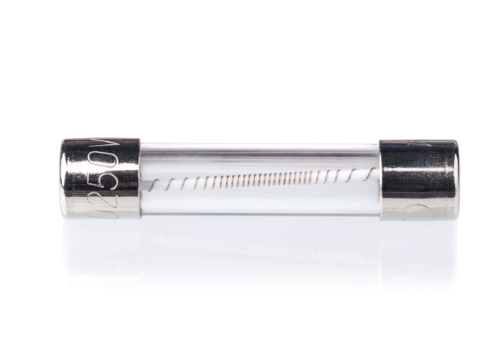
Regarding electrical safety, fuses are a key player in protecting your circuits from overcurrent conditions. These tiny but mighty components are designed with a thin wire or filament that acts as a defense mechanism. If a current exceeds a specific level, the wire will melt or break, thus stopping the flow of electricity and preventing any damage to other components. This sacrificial action not only protects the circuit but also minimizes the risk of fire and electrical shock.

Fuses are the unsung superheroes of various applications, such as power supplies, lighting, and automotive systems. They are essential in household appliances, industrial machinery, and even in delicate electronic devices. But not all fuses are created equal! They come in multiple types, including fast-blow, slow-blow, and resettable fuses, each with unique attributes.Ā 

Fast-blow and slow-blow fuses serve similar purposes but are designed to handle different types of electrical conditions.

Fast-blow fusesĀ react almost instantly to overcurrent conditions. They are designed to protect sensitive electronic components that could be damaged by even brief surges of current. When the current exceeds the fuseā€™s rated capacity, the thin wire inside the fast-blow fuse melts quickly, interrupting the circuit.Ā These fuses are ideal for applications where a rapid response is crucial, such as in delicate electronic devices like computers, audio equipment, and other consumer electronics.

Slow-blow fuses, also known as time-delay fuses, are designed to tolerate temporary surges of current without blowing. This makes them suitable for circuits that experience short-term inrush currents, such as those found in motors, transformers, and power supplies. The wire inside a slow-blow fuse is thicker and sometimes coiled, allowing it to withstand higher currents for a short period before melting.Ā This delay prevents the fuse from blowing during normal, brief surges, such as when a motor starts up.

Here are some key differences:

  • Response Time: Fast-blow fuses react immediately to overcurrent, while slow-blow fuses allow for a short delay.
  • Applications: Fast-blow fuses are used in sensitive electronic devices, whereas slow-blow fuses are used in applications with inrush currents, like motors and transformers.
  • Construction: Fast-blow fuses have a thin wire that melts quickly, while slow-blow fuses have a thicker wire or a coiled wire that can handle short bursts of high current.

Choosing the right type of fuse depends on the specific requirements of the circuit you are protecting. Using the correct fuse type ensures both safety and functionality of the electrical system.

Fuses are also available in different current and voltage ratings, ensuring that there are options to fit any application. TheĀ current ratingĀ indicates the maximum current the fuse can handle without blowing, while theĀ voltage ratingĀ specifies the maximum voltage the fuse can safely interrupt.Ā Additionally, fuses are characterized by theirĀ breaking capacity, which is the maximum fault current they can interrupt without being destroyed.

Next time you need extra protection for your electrical system, consider turning to the trusty fuse. Whether itā€™s safeguarding your home electronics, ensuring the reliability of industrial equipment, or protecting automotive circuits, fuses provide a simple yet effective solution for overcurrent protection.

10. Circuit Breaker

electrical element: circuit breaker

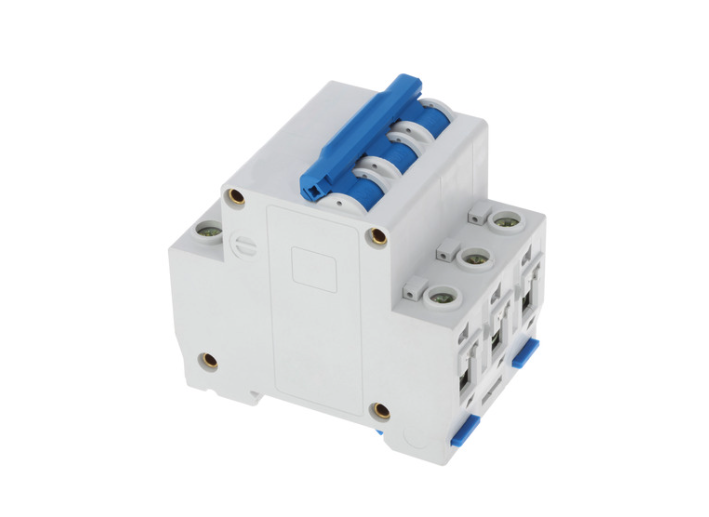
A powerful ally in electrical engineering, circuit breakers work tirelessly to protect circuits from the dangers of overcurrent conditions. They heroically interrupt current flow when levels exceed a predetermined threshold, saving the day for everything from household wiring to industrial machinery. Circuit breakers are designed to automatically disconnect the electrical circuit when they detect an overload or short circuit, preventing potential damage, overheating, and fire hazards.

Browse Circuit Breakers

With different types, current and voltage ratings available, circuit breakers offer unparalleled flexibility for a wide range of applications.Ā 

  • Thermal-magnetic circuit breakerscombine both thermal and magnetic trip mechanisms. The thermal part responds to prolonged overcurrent conditions by bending a bimetallic strip, while the magnetic part reacts instantly to short circuits using an electromagnet.Ā 
  • Magnetic-only circuit breakersrely solely on the magnetic mechanism, making them ideal for applications where rapid response to short circuits is critical
  • Electronic circuit breakersuse electronic components to detect overcurrent conditions and can offer more precise protection settings and advanced features like remote monitoring and control

Circuit breakers are also categorized by theirĀ current and voltage ratings, which determine the maximum current and voltage they can safely interrupt Low-voltage circuit breakersĀ are commonly used in residential and commercial buildings, whileĀ medium– and high-voltage circuit breakersĀ are used in industrial and utility applications to protect electrical grids and large machinery. Ā Additionally, circuit breakers can be classified based on theirĀ breaking capacity, which is the maximum fault current they can interrupt without being damaged.

Whether you need thermal-magnetic, magnetic-only, or electronic circuit breakers, they are always ready to protect your system from harm. Unlike fuses, circuit breakers can be reset and reused after tripping, adding to their convenience and reliability.Ā Circuit breakers are essential in ensuring electrical systems’ safety and efficiency across various sectors.

11. Battery

As a vital energy source for numerous electrical devices, batteries are integral to our daily lives. These devices convert chemical energy into electrical energy through one or more cells, allowing them to power everything from portable gadgets to electric vehicles.Ā Batteries consist of two electrical terminals called the cathode and the anode, separated by an electrolyte that facilitates the flow of ions, enabling the chemical reactions that produce electrical energy.

Browse Batteries

With an array of battery types available, including alkaline, lithium-ion, lead-acid, and nickel-cadmium, users can choose the correct voltage and capacity to suit their needs.Ā 

  • Alkaline batteriesare commonly used in household items like remote controls and flashlights due to their long shelf life and reliability.
  • Lithium-ion batteriesĀ are popular in portable electronics and electric vehicles because of their high energy density and rechargeability.
  • Lead-acid batteriesĀ are often found in automotive applications and backup power systems, valued for their durability and cost-effectiveness
  • Nickel-cadmium batteries, though less common today due to environmental concerns, are still used in some power tools and emergency lighting systems for their ability to deliver high discharge rates.

Batteries are also classified intoĀ primaryĀ andĀ secondaryĀ types.Ā 

Primary batteriesĀ are single-use and cannot be recharged, making them suitable for low-drain devices.

Secondary batteries, or rechargeable batteries, can be recharged multiple times, making them ideal for high-drain applications and reducing environmental impact.

Whether you rely on batteries for backup power or to keep your devices going, these power-packed components have become an indispensable part of our modern world.Ā Advances in battery technology continue to drive innovation, leading to more efficient, longer lasting, and environmentally friendly energy storage solutions.

12. Switch

A switch is an electrical component used to open or close a circuit. It comprises a set of contacts that can be manually or electronically operated. When the contacts are closed, they allow current to flow through the circuit; when open, they interrupt the current flow. Switches are used in a variety of applications, such as lighting systems, power supplies, and home appliances. They play a crucial role in controlling the operation of electrical devices, providing a simple means to turn them on or off.

Browse Switches

Switches come in various types, including rocker, toggle, and pushbutton.Ā 

  • Rocker switches are commonly used in household appliances and power strips, featuring a rocking mechanism that moves back and forth to open or close the circuit.Ā 
  • Toggle switches are often found in industrial and automotive applications, characterized by a lever that is flipped up or down.
  • Pushbutton switches are used in devices like calculators and control panels, where a button is pressed to make or break the connection.

In addition to these common types, there are alsoĀ 

  • Rotary switches which are used in equipment like multi-speed fans and range selectors.
  • Slide switches which are often found in small electronic devices like remote controls
  • Reed switchesĀ are another type, activated by a magnetic field and used in applications such as security systems and proximity sensors.

Depending on the application, switches are also available in different contact and voltage ratings. TheĀ contact ratingĀ indicates the maximum current and voltage the switch can handle without damage, while theĀ voltage ratingĀ specifies the maximum voltage the switch can safely interrupt. Switches can also be classified by theirĀ pole and throw configurations.Ā For example, aĀ single-pole single-throw (SPST)Ā switch controls one circuit with one on/off position, while aĀ double-pole double-throw (DPDT)Ā switch can control two circuits and switch between two positions.

Switches are integral to the functionality and safety of electrical systems, ensuring that devices operate as intended and can be easily controlled by users.

Safety Considerations when Choosing a Switch for a High Voltage Circuit

When choosing a switch for high-voltage circuits, several safety considerations are crucial to ensure reliable and safe operation:

  • Voltage and Current Ratings: Ensure the switch is rated for the maximum voltage and current it will handle.Ā Using a switch with insufficient ratings can lead to arcing, overheating, and potential failure.
  • Insulation and Clearance: High-voltage switches require adequate insulation and clearance to prevent electrical arcing and ensure safe operation.Ā This includes proper spacing between contacts and the use of insulating materials that can withstand high voltages.
  • Breaking Capacity: The switch must have a breaking capacity that exceeds the maximum fault current it might encounter.Ā This ensures the switch can safely interrupt the circuit without damage during fault conditions.
  • Safety Barriers and Enclosures: High-voltage switches should be housed in enclosures that provide physical protection and prevent accidental contact.Ā Safety barriers can also help contain any arcs or sparks that may occur.
  • Thermal Management: High-voltage switches can generate significant heat, so proper thermal management is essential.Ā This includes using materials and designs that dissipate heat effectively and prevent overheating.
  • Compliance with Standards: Ensure the switch complies with relevant safety standards and regulations, such as those set by the National Electrical Manufacturers Association (NEMA) and the International Electrotechnical Commission (IEC).Ā Compliance ensures the switch meets safety and performance criteria.
  • Emergency Shutoff: High-voltage systems should include an easily accessible emergency shutoff mechanism to quickly disconnect power in case of an emergency.
  • Regular Maintenance and Inspection: Regular maintenance and inspection are vital to ensure the switch remains in good working condition.Ā This includes checking for signs of wear and corrosion and ensuring all connections are secure.

13. Oscillator

An oscillator is a nifty electrical gadget that can produce a steady, buzz-worthy electrical signal with a specific frequency. This device uses a resonant circuit that generates a constant frequency signal. Oscillators are a jack-of-all-trades component and can be found in practical uses like radios, clocks, and test gear.Ā They work by converting direct current (DC) from a power source into an alternating current (AC) signal, maintaining a consistent waveform without needing an external input.

Oscillators come in various types, each suited to different applications.Ā 

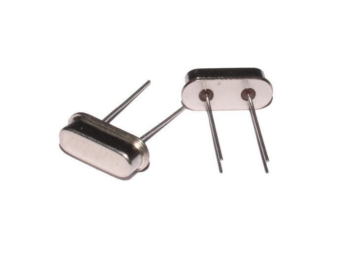
  • Crystal oscillatorsĀ use a quartz crystal to stabilize the frequency, making them ideal for precise timing applications like watches and communication devices.Ā 
  • RC oscillatorsĀ (resistor-capacitor) are used in audio and low-frequency applications due to their simplicity and ease of tuning.
  • LC oscillatorsĀ (inductor-capacitor) are common in radio frequency (RF) applications, providing high-frequency stability.

The frequency range of oscillators can vary widely to suit multiple applications. For instance,Ā low-frequency oscillators (LFOs)Ā are used in audio synthesis and modulation, whileĀ high-frequency oscillatorsĀ are essential in RF communication and microwave systems. Voltage-controlled oscillators (VCOs)Ā allow the frequency to be adjusted by varying the input voltage, making them versatile for applications like signal generators and phase-locked loops.

Oscillators are also critical in digital electronics, whereĀ clock oscillatorsĀ provide the timing signals that synchronize operations in microprocessors and digital circuits. Relaxation oscillators, which generate non-sinusoidal waveforms like square or sawtooth waves, are used in applications such as blinking lights and pulse generation.

Notably, oscillators are designed to maintain a stable frequency despite variations in temperature, load, and power supply, ensuring reliable performance in diverse environments.Ā This versatility and reliability make oscillators indispensable in modern electronics, from everyday gadgets to sophisticated industrial equipment.

What is the Difference between Single-ended and Differential Outputs in Oscillators?

The difference between single-ended and differential outputs in oscillators lies in how the signals are transmitted.Ā Single-ended outputsĀ use one signal line and a ground reference. This means the signal is measured relative to the ground, which can make it more susceptible to noise and interference from external sources.

Ā In contrast,Ā differential outputsĀ use two complementary signal lines, where the signal is transmitted as the difference between these two lines. This configuration enhances noise immunity because any noise that affects both lines equally is canceled out when the difference is taken. Differential outputs are particularly advantageous in high-frequency applications and environments with significant electrical noise, as they provide better signal integrity and reduce the likelihood of errors. This makes differential outputs a preferred choice in precision communication systems, high-speed data transmission, and other critical applications where maintaining signal quality is paramount.

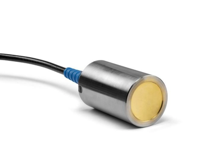
14. Transducer

A transducer is an electrical component that is used to convert one form of energy into another format of energy. It can convert electrical power into mechanical energy or vice versa. Transducers are used in various applications, such as microphones, loudspeakers, and sensors.Ā For example, a microphone converts sound waves (mechanical energy) into electrical signals, while a loudspeaker does the reverse, converting electrical signals into sound waves.

Browse Transducers

Transducers come in various types, including piezoelectric, electromagnetic, and thermoelectric transducers.Ā Piezoelectric transducersĀ use materials like quartz that generate an electrical charge when mechanically stressed. They are commonly used in applications such as ultrasound imaging and vibration sensors.Ā Electromagnetic transducersĀ operate based on electromagnetic induction, where a change in magnetic field induces an electrical current.Ā These are found in devices like dynamic microphones and speakers. Thermoelectric transducersĀ convert temperature differences directly into electrical voltage using the Seebeck effect and are used in thermocouples for temperature measurement.

Depending on the application, transducers are also available in different sensitivity and frequency ranges.Ā 

SensitivityĀ refers to the transducerā€™s ability to convert a small amount of input energy into a measurable output signal, which is crucial for applications requiring precise measurements.

Frequency rangeĀ indicates the range of frequencies over which the transducer can effectively operate, which is important for applications like audio equipment and communication systems.

Transducers can also be classified asĀ activeĀ orĀ passive.

Ā Active transducersĀ generate electrical signals directly in response to an external stimulus, such as a thermocouple generating voltage from a temperature difference.

Ā Passive transducers, on the other hand, require an external power source to operate and produce a change in some passive electrical quantity, such as resistance or capacitance.

These versatile components are integral to modern technology, enabling the conversion and measurement of various physical phenomena, and are essential in fields ranging from medical diagnostics to industrial automation.

How to Choose the Right Sensitivity for a Pressure Transducer?

Choosing the right sensitivity for a pressure sensor involves several key considerations to ensure accurate and reliable measurements for your specific application:

  1. Application Requirements: Determine the specific requirements of your application. Consider the range of pressures you need to measure, and the level of precision required.Ā For example, high-precision applications like laboratory measurements may require sensors with higher sensitivity compared to industrial applications.
  2. Pressure Range: Select a sensor with a pressure range that matches your applicationā€™s needs.Ā Aim to use at least 25% and at most 80% of the sensorā€™s full scale to ensure good resolution and accuracy. For instance, if you need to measure pressures between 0 and 5 bar, a sensor with a range of 0-20 bar would be more appropriate than one with a range of 0-100 bar.
  3. Environmental Conditions: Consider the environmental conditions where the sensor will be used. Factors such as temperature, humidity, and exposure to corrosive substances can affect sensor performance.Ā Choose a sensor with materials and construction that can withstand these conditions.
  4. Dynamic Range and Response Time: Evaluate the dynamic range and response time of the sensor.Ā Applications with rapidly changing pressures may require sensors with fast response times and high dynamic ranges to accurately capture transient events.
  5. Calibration and Stability: Ensure the sensor offers good calibration stability over time.Ā Some sensors come pre-calibrated and temperature compensated, which can save time and improve reliability. Ā Check for any potential drift in sensor readings and choose a sensor with minimal drift for long-term accuracy.
  6. Compatibility with Media: Ensure the sensorā€™s wetted materials are compatible with the media being measured.Ā Incompatible materials can lead to sensor damage or inaccurate readings.

Thanks for Diving In!

Understanding the essential electrical elements is fundamental to grasping the complexities of modern electronics. From the tiny yet powerful integrated circuits that drive our digital world to the versatile transducers that convert energy forms, each component plays a crucial role in the functionality and innovation of electronic devices. Relays, fuses, circuit breakers, and oscillators each bring unique capabilities and protections, ensuring the safety, efficiency, and reliability of electrical systems. As technology continues to advance, a solid knowledge of these foundational electrical elements will remain vital for anyone involved in electrical engineering, design, or maintenance. By delving deep into these components, we not only appreciate their individual contributions but also gain a view of how they collectively power and protect our everyday lives.

Share this post
Facebook
Twitter
LinkedIn
WhatsApp
Email

Disclaimer: The opinions, beliefs, and viewpoints expressed by the various authors and/or forum participants on this website do not necessarily reflect the opinions, beliefs, and viewpoints of Microchip USA or official policies of Microchip USA.