What is a Diode? A Simple Overview

More from the Category
Diodes are a critical part of modern electronics because they serve a fundamental role in controlling the flow of electricity in countless devices we use in our everyday lives. Let's dive in.
What is a Diode?
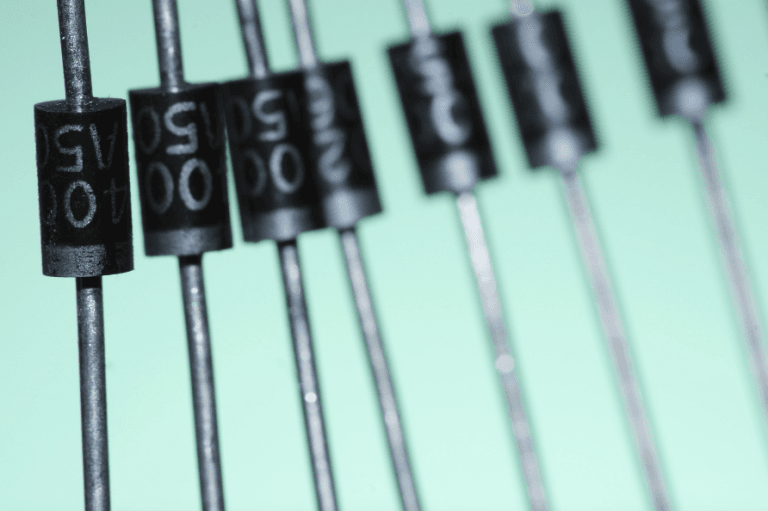
At its core, a diode is a semiconductor device that allows current to flow in one direction while preventing its flow in the opposite direction. This unique property makes diodes essential for managing electrical signals and protecting circuits.
Interested in learning about other types of electronic components? Check out this article!
How Do Diodes Work?
Diodes are generally constructed from two types of semiconductor materials: p-type (positive) and n-type (negative). When these materials are joined together, they form a p-n junction. The behavior of this junction gives the diode its ability to control the direction of current flow.
When a voltage is applied in the forward direction (positive to the p-type, negative to the n-type), the diode becomes forward-biased, allowing current to flow freely. In this state, the diode acts as an efficient conductor.
When the voltage is reversed, the diode becomes reverse-biased. It acts as an insulator and resists the flow of current. This ability to allow or block current depending on the direction of voltage is what makes diodes so valuable in electronic circuits.
Understanding these basic operating principles is essential for anyone working with electronic components, as diodes play a vital role in ensuring circuits function properly.
Polarity
The polarity of a diode is determined by its two leads: the anode and the cathode. These terminals dictate the direction in which the diode can conduct current.
· Anode: The positive terminal. A positive voltage must be applied here for the diode to conduct.
· Cathode: The negative terminal. This must be at a lower potential than the anode for current to pass through the diode.
Correct orientation is critical. If the diode is installed backward, it will block current flow instead of allowing it.
Diode Ratings
Diodes are specified by several important ratings. Understanding these ratings helps ensure the diode functions correctly in your circuit.
· Type of Diode: Includes rectifier, Zener, Schottky, and light-emitting diodes (LEDs), each designed for a particular function.
· Voltage Rating: The peak inverse voltage (PIV) indicates how much reverse voltage the diode can handle before breakdown.
· Current Capacity: The forward current rating defines how much current the diode can conduct safely in the forward direction.
Using a diode outside its rated limits can lead to failure or reduced performance.
What Happens When a Diode Exceeds Its Current Rating?
If a diode conducts more current than it is rated for, it can fail in one of two ways:
· Short Circuit Condition: The diode allows current in both directions, losing its ability to block reverse flow.
· Open Circuit Condition: The diode stops conducting altogether and behaves like a broken wire.
Both conditions compromise the performance of the circuit and can lead to component damage.
Types of Diodes

There are several types of diodes, each suited to specific applications:
Standard Diodes: Used in rectification circuits to convert AC to DC.
• Applications: Power supplies, chargers, and basic electronic circuits.
Zener Diodes: Allow reverse current flow at a defined voltage, making them useful for voltage regulation.
• Applications: Voltage regulation and overvoltage protection.
PIN Diodes: Contain a wide intrinsic layer and are used in radio-frequency applications and optical communication.
• Applications: Radio-frequency (RF) switches and optical communication systems.
Schottky Diodes: Characterized by low forward voltage drop and fast switching. Common in high-speed and RF circuits.
• Applications: High-speed circuits, RF applications, and power rectifiers.
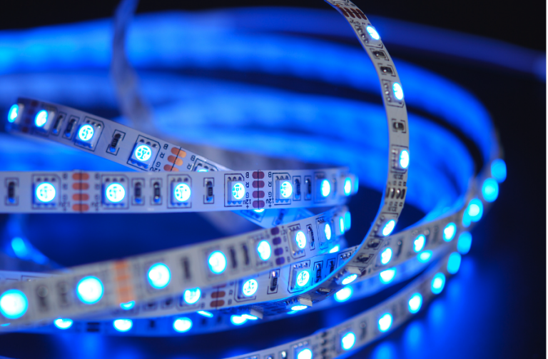
Light Emitting Diodes (LEDs): Emit light when forward-biased. Widely used in displays and lighting.
• Applications: Displays, indicators, and general lighting.
Laser Diodes: Produce coherent light for communication, medical, and consumer applications.
• Applications: Optical communication, medical instruments, and consumer electronics.
Photodiodes: Generate current in response to light. Essential in solar panels and light sensors.
• Applications: Solar cells, light sensors, and optical systems.
Varactor Diodes: Operate as variable capacitors, used in tuning circuits and frequency modulation.
• Applications: Tuning circuits, frequency modulation in RF design.
Tunnel Diodes: Exhibit negative resistance and are used in high-speed switching and oscillators.
• Applications: High-speed switching, oscillators, and microwave applications.
Transient Voltage Suppressor (TVS) Diodes: Protect circuits from sudden voltage spikes.
• Applications: Surge protection in automotive, telecom, and industrial electronics.
Testing Diodes
A digital multimeter can test a diode’s functionality using the diode test mode. This mode applies a small voltage across the diode and measures the result.
To test:
1. Forward-Bias Test: Set the multimeter to diode mode. Connect the positive lead to the anode and the negative lead to the cathode. A working diode will show a voltage drop between 0.5 and 0.8 volts.
2. Check Resistance: A good diode shows forward-bias resistance between 10 ohms and 1000 ohms.
3. Reverse-Bias Test: Reverse the leads. The multimeter should display “OL” or another indicator of high resistance, confirming the diode is blocking reverse current as intended.
What Should be the Forward-Biased Resistance of a Good Diode?
A healthy diode typically has a forward-biased resistance between 10 ohms and 1000 ohms. This resistance range ensures that the diode allows current to pass efficiently when forward-biased while maintaining proper functionality.
What Does a Digital Multimeter Display When a Diode is Reverse-Biased?
When a diode is reverse-biased and tested with a digital multimeter, the screen should display “OL,” meaning "open loop" or infinite resistance. This reading confirms that the diode is not conducting in the reverse direction, which is normal and desired behavior.
Diode Symbols
Understanding how diodes are represented in schematics is important for reading and designing circuits.
Standard Diode: A triangle pointing toward a line. The triangle denotes the p-type material, and the line denotes the n-type.
Zener Diode: Similar to the standard diode but with bent lines at the cathode end to indicate voltage regulation.
LED: Includes two small arrows pointing away from the triangle, representing light emission.
Photodiode: Has arrows pointing toward the triangle, indicating light detection.
Schottky Diode: Often drawn like a standard diode with slight modifications to indicate its unique characteristics.
Diode Symbol’s Arrow Pointing Against Electron Flow
The arrow in the diode symbol points in the direction of conventional current flow, from positive to negative, even though actual electron flow goes from negative to positive. This convention was established before the discovery of electron movement and remains standard in engineering diagrams.
This choice:
· Reflects the traditional understanding of current
· Aligns the direction of arrows across all semiconductor symbols
· Promotes consistency in circuit schematics
Applications of Diodes

Diodes play essential roles in a wide range of applications across industries.
In power supplies, standard diodes convert AC to DC. Zener diodes help maintain a stable voltage, protecting sensitive components. In communication systems, diodes are used to demodulate amplitude-modulated (AM) signals, ensuring clear reception.
LEDs have revolutionized lighting by offering energy-efficient solutions for homes, vehicles, and streetlights. TVS diodes protect sensitive electronics from voltage surges. Varactor diodes support RF tuning and frequency modulation in communication equipment.
By selecting the right type of diode for a given application, engineers can improve circuit reliability and performance.
Get the Diodes and Components You Need at Microchip USA
Diodes are indispensable to the function of modern electronics. Their ability to control and direct current makes them a foundational component in many applications, from power conversion to advanced communication systems.
If you’re looking for integrated circuits or components to pair with your diodes, Microchip USA can help. Our team specializes in supplying hard-to-find and obsolete parts, ensuring you get the components you need, on time and at a competitive price.
Contact us today to learn how we can support your next project.


